1.1Outdoor energy storage system;
Total installed capacity: PV capacity 51.3kW, energy storage system configured at 30 kW / 50KWh ;
Operating environment: The inverter and energy storage system are installed in outdoor container cabinets and adopt natural convection cooling.
Battery charge and discharge: below 1C, 1 to 2 hours of backup power;
Topology of the Photovoltaic Storage Integration

The operation strategy of the "PV-storage integrated" project:
When the load power is higher than the photovoltaic generation power, the power station will generate power for its own use;
When the photovoltaic power is higher than the load power, the battery will start to charge;
The energy storage system will be discharged to 80% of the energy storage capacity during the daily peak power period
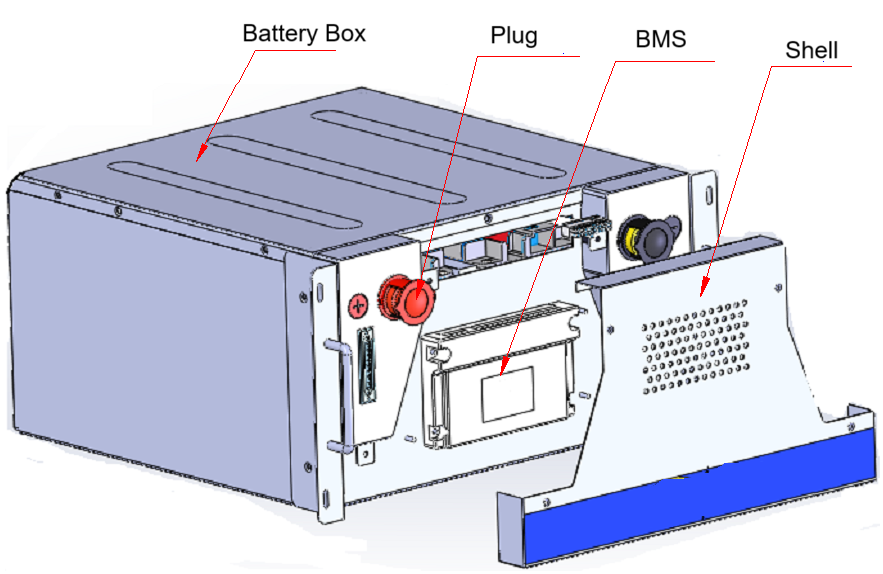
The battery module is a high-safety, long lifespan lithium iron phosphate battery(LiFePO4), which has the characteristics of standardization, modularization, easy installation and maintenance, etc.
BroVolt is a LFP battery manufacturer .So we made this battery according to project needs.This LiFePO4 battery is assembled into a PACK using laser welding technology. The battery PACK box is 2P16S, and the parameters are 51.2V/200Ah (10.24kWh). The capacity is 51.2V/200Ah*5S=256V/200Ah (51.2kWh), and the battery system voltage range is 224V~292V
51.2kWh Energy Storage System Parameter Table:
Project | Parameter |
Energy | 51.2kWh , 25℃@ 0.5C |
Nominal Voltage | 514.4 V |
Operating Voltage | 537.6 V ~700.8 V |
Conversion Efficiency | DC side ≥ 97.1 % |
Communication | BMS: CAN/RS485 |
Balanced | Passive Balance |
Maximum Discharge Current | Current: 200A |
Altitude | Below 4500 |
2.1.2 Battery performance
LFP battery: capacity 100Ah, nominal voltage 3.2V, operating voltage range 2.8 ~ 3.65V, self-discharge rate ≤ 3%,
No | Item | Specification |
1 | Dimension | 442 mm (W)*565 mm (D)* 245 mm (H) |
2 | Nominal capacity | 200Ah |
3 | Nominal voltage | 51.2V |
4 | Operating voltage | 4 4.8~ 58.4 V |
5 | Maximum charging rate | Max 1 C @25 ℃ |
6 | Maximum discharge rate | Max 1C @25 ℃ |
7 | Weight | About 108kg |
8 | Nominal energy | 10.24 kWh |
Battery module appearance introduction:
The battery cluster consists of 5 standard battery modules with specifications of 2P16S, a capacity of 51.2 kWh, a nominal voltage of 256 V, an operating voltage range of 224 V to 292 V, and a total mass of approximately 1.1 T.
No | Equipment | Quantity | Unit |
1 | U Box | 5 | set |
2 | BMU | 1 | set |
3 | High voltage box | 1 | set |
4 | BCU | 1 | set |
5 | Power Cable | 1 | set |
6 | Power distribution cable | 1 | set |
7 | Busbar | 6 | set |
Ensure that the strength of the battery cluster and battery module rack meets the domestic Class IV highway transportation standards.
When transporting the battery cluster, the communication harness, busbar and power line outside the module must be removed, and the high-voltage box should be unplugged and disconnected.
No. | Item | Specification |
1 | Battery cluster size | 1400 mm(W)*700 mm(D)*2250 mm(H) |
2 | Nominal capacity | 200Ah @ 0.25 C |
3 | Nominal voltage | 256 V |
4 | Operating voltage range | 224V ~ 292V |
5 | Maximum charging rate | 1 C@25 ℃ |
6 | Maximum discharge rate | 1C@25 ℃ |
7 | Weight | 108kg /single box |
8 | Nominal energy | 51.2 kWh |
9 | Insulation standards | Battery box insulation resistance ≥500MΩ (1000VDC) |
10 | Withstand voltage standard | 3110VDC, no breakdown phenomenon, Leakage current <20mA |
11 | Charge Cut-off Voltage | 3.65 V |
12 | Discharge Cut-off Voltage | 2.8V |
1 3 | Charging temperature | 0℃- 45 ℃ |
1 4 | Discharge temperature | -20℃-55℃ |
2.1.5 PCS Parameter
DC side | |
DC voltage | 200V~700V |
DC Max current | 90A |
DC Max power | 33kW |
AC side | |
Output voltage | 380V/400V, 3P4W |
Friquency | 50Hz/60Hz |
Nominal current | 43A |
THDI | 3≤% |
Power factor | 0.8(leading)~0.8(lagging) |
System | |
Effeciency | 97% |
Cooling method | Force air cooling |
Noise | 70db |
Protection rate | IP20 |
The battery cluster high-voltage control system is equipped with a total positive contactor, pre-charging circuit, fuse, molded case circuit breaker, etc. The contactor is automatically controlled byBMS to manage and control the battery charging and discharging.
No | Electrical Equipment | Remark |
1 | MCCB | Used for protection and emergency cutoff of the entire circuit |
2 | Breaker | Used for circuit control on and off |
3 | BCU | Control Devices |
4 | Connectors | Power cable input and output |
5 | Pre-charge resistance | Pre-charge circuit |
6 | Shunt | Current acquisition |
7 | Fuse | For protection of the entire circuit |
8 | UPS | 12VDC |
The high-voltage control box has built-in single-circuit relays, circuit breakers, and fast fuses. A relay is installed in the total positive circuit of the battery cluster to ensure that under the emergency cut-off command of the BMS, the live circuit of the battery cluster can be safely and quickly cut off during charging or discharging to ensure the safety of the battery cluster; the circuit breaker can be directly disconnected manually in an emergency and during later maintenance, playing the role of a switch circuit, which has better simplicity and safety; the fast fuse can ensure that the ground circuit is quickly cut off when a short circuit or high current occurs in the battery cluster circuit, ensuring the safety of the battery cluster.
1) High-precision monitoring and reporting of battery analog quantity
It includes battery cluster real-time voltage detection, battery cluster charge and discharge current detection, single cell terminal voltage detection, battery pack multi-point temperature detection, and battery cluster insulation monitoring.
2) Battery system operation alarm, alarm local display and reporting function.
Including battery system overvoltage alarm, battery system undervoltage alarm, battery system overcurrent alarm, battery system high temperature alarm, battery system low temperature alarm, battery system leakage alarm, battery management system communication abnormality alarm, battery management system internal abnormality alarm.
3) Battery system protection function
When analog quantities such as voltage, current, and temperature in the battery system exceed safety protection thresholds, the battery management system will isolate the fault, remove the problematic battery cluster from operation, report protection information, and display it locally.
4) Self-diagnosis function
This battery management system has a self-diagnosis function. When the internal communication or external communication of the battery management system is interrupted, it can report a communication interruption alarm. In addition, it also has the function of fault self-diagnosis, local display and reporting to the on-site monitoring system for other abnormalities such as analog quantity acquisition abnormalities.
5) Equalization function
This battery management system uses a passive balancing strategy to ensure the consistency of the cells inside the system battery.
6) Operation parameter setting function
7) Relay forced control (engineering mode)
The control function can be used to force the charging and discharging relays to close.
8) The battery management system can display the various operating states of the battery system locally .
This project uses XX Power Supply Station to build a photovoltaic power station. The usable area of the roof is 550 square meters, the installed capacity is 51.3 kWp, and 450Wp monocrystalline silicon modules are used , with a preliminary total of 114 modules .
The bird's-eye view and component layout of the actual on-site survey are as follows :
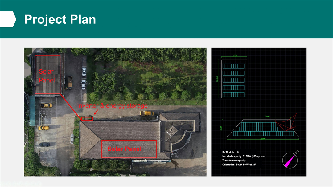
The total installed capacity of the solar generation system of this project is 51.3kWp, which consists of 1 solar power generation subsystem, each solar power generation subsystem consists of several photovoltaic power generation units; each photovoltaic power generation unit consists of several solar panel arrays and a single string inverter. This project has a total of about 1 solar power generation unit.
The design of a typical solar power generation collection line is as follows: 18 to 20 monocrystalline silicon photovoltaic modules are connected in series to form a single string circuit; several photovoltaic strings are connected to a single string inverter; several string inverters are connected to a single AC combiner box; several AC combiner boxes are connected to a single low-voltage grid-connected cabinet (the AC combiner box can also be omitted depending on the distance. In this case, the string inverter output line is directly connected to the low-voltage grid-connected cabinet).
Each photovoltaic power generation unit includes a string inverter and corresponding multiple groups of photovoltaic module strings, DC connecting cables, etc.
The number of PV strings in series is mainly selected based on the PV module parameters, inverter parameters and system capacity. The design is mainly based on the following principles:
(1) Under the operating environment, the maximum open-circuit voltage of the PV module string should be less than the maximum DC input voltage allowed by the PV inverter;
(2) The operating voltage of the PV module will be affected by the module temperature. The operating voltage at different temperatures is different. The operating voltage under different working conditions should be within the inverter MPPT range.
According to the PV module parameters and PV inverter parameters selected above, the maximum allowable DC input voltage of the inverter is 1100V. Combined with the on-site environmental conditions of this project and the predicted operating temperature of the modules, the above principles are used for calculation and comparison. This project uses 340Wp monocrystalline silicon modules for calculation. The specific formula is as follows:
Where:
Voc——open circuit voltage of photovoltaic cell module (V);
t——the extreme low temperature under the working conditions of photovoltaic cell (℃);
KV——open circuit voltage temperature coefficient of photovoltaic cell ;
N——The number of photovoltaic cell modules connected in series (N is rounded down);
Vdcmax——The maximum DC input voltage allowed by the inverter (V).
Vmpptmin——Minimum voltage of inverter maximum power tracking range
Vmpptmax——the maximum voltage of the inverter maximum power tracking range,
Vpm——The working voltage of photovoltaic modules under STC test conditions
——The temperature coefficient of the operating voltage of the photovoltaic module. If this data is not available, KV can be used instead.
——The extreme high temperature under the working conditions of photovoltaic modules (degrees celsius).
According to solar panel parameters and operating environment, it can be calculated that N≤25, 7≤N≤25.
In order to increase the output voltage of the string and reduce line losses, a larger value should be selected for the number of solar panel connected in series. At the same time, the DC side insulation withstand voltage and the optimized design of the fixed bracket and the layout of the array should be considered. Based on the above factors, this project plans to use 20 pieces of 340Wp monocrystalline silicon solar cell photovoltaic modules in series to connect to the inverter.
The wiring system of the solar generation system is divided into a DC system and an AC system. The DC system refers to the system composed of the photovoltaic module and the DC side of the inverter input.
The total installed capacity of the photovoltaic power generation system of this project is 51.3 kWp, which consists of 1 photovoltaic power generation subsystem, each photovoltaic power generation subsystem consists of several photovoltaic power generation units; each photovoltaic power generation unit consists of several photovoltaic module arrays and 1 string inverter. This project has a total of about 1 solar power generation unit.
This project is low voltage grid-connected and is connected to the grid via 380V transmission.
The access system solution for this project:
The grid connection method is self-generation and self-use, and the surplus power is connected to the grid. A total of 1 grid connection point is set up, and a low-voltage grid connection cabinet is connected to the low-voltage distribution room in the factory area. The grid connection cabinet is connected to the original low-voltage busbar of the enterprise distribution cabinet through cable connection or direct splicing of busbars. According to the different grid connection capacities, the corresponding specifications of cables or busbar are selected. The actual grid connection method is determined according to the actual situation on site.
1. Main transformer
This project is connected to the grid at 380V, and the original transformer capacity at the grid connection point meets the requirements for photovoltaic grid connection.
2. Scale of outgoing lines
The photovoltaic power generation of this project is connected to the low-voltage grid-connected cabinet after inverter confluence. The outgoing cables of the grid-connected cabinet use AC cables of corresponding specifications according to the capacity of the connected inverter or AC combiner box (if any).
3. Main electrical connection
This project is a low-voltage grid-connected project. The grid-connected cabinet is connected to the original low-voltage busbar of the enterprise's power distribution cabinet through cable connection or direct copper busbar splicing. Depending on the grid-connected capacity, the corresponding specifications of cables or copper busbars are selected. The actual grid-connected method is determined according to the actual situation on site.
4. Line capacitance current compensation
This project is a low-voltage grid-connected project and line capacitance current compensation may not be considered.
5. Short circuit level of electrical equipment
The short-circuit level of the grid-connected cabinet in the low-voltage distribution room shall refer to the design of the low-voltage cabinet on the original busbar.
The design of the photovoltaic module support system must be based on the geographical, climatic and solar energy resource conditions of the construction site, and scientifically plan the support structure that fixes the photovoltaic modules in a certain direction, arrangement and spacing, so that the entire photovoltaic power generation system can achieve the maximum power output while meeting the design requirements of wind, snow load, load bearing, earthquake resistance, etc. The support is usually a steel structure and an aluminum alloy structure, or a mixture of the two.
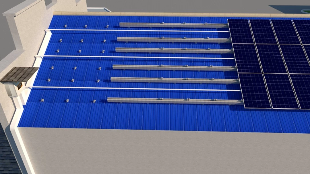
Color steel tile roof components are fixed and installed with aluminum alloy rails, and are generally installed in a flat manner along the natural slope of the roof. The aluminum alloy rails are made of lightweight Al6063-T6 anodized aluminum alloy, and the bracket system is designed according to GB50797 standard, with sandblasting and oxidation treatment on the surface, and a thickness of 15UM.
The aluminum rail is reliably fixed on the color steel tile by a special aluminum alloy clamp. According to the different types of color steel tiles, the clamp can be divided into different types such as corner type and vertical lock type, which can be selected according to the actual situation of the construction site. When a larger span of aluminum rail is required, the aluminum rails are fixed with connecting strips and flange bolts.
The soalar panel are laid flat on the aluminum rail with an edge extension of 100 mm and fixed with a single-sided pressing block combination and a double-sided pressing block combination.
The schematic diagram is as follows:
Figure 1. Schematic diagram of color steel
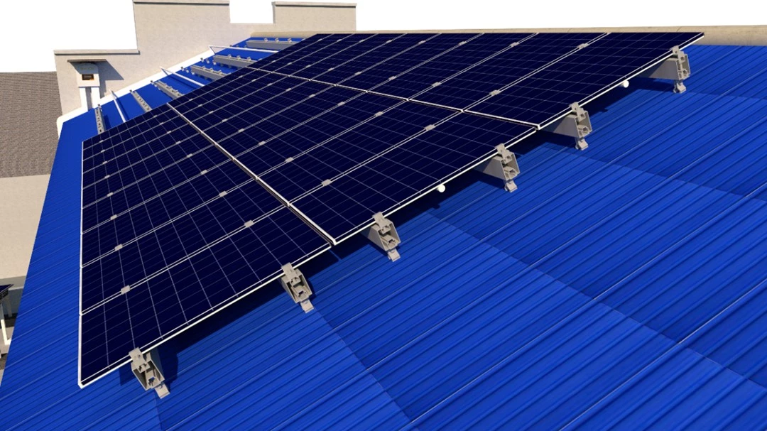
Figure 2. Schematic diagram of color steel tile roof installation
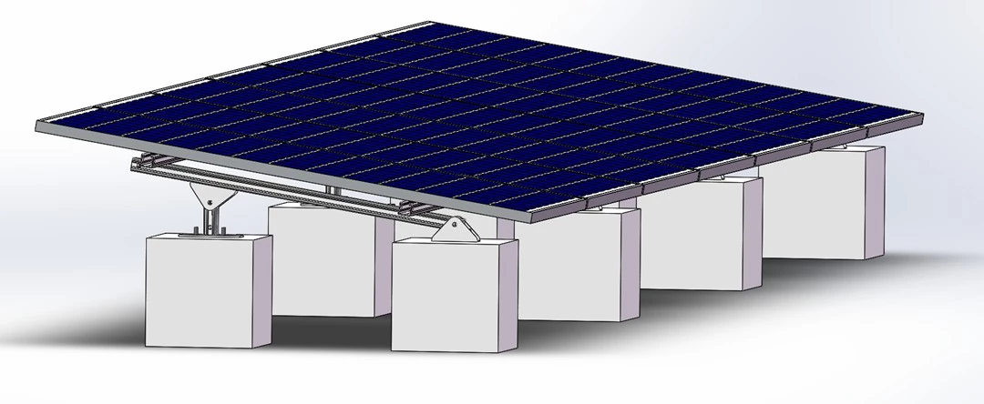
The concrete roof uses a galvanized steel structure fixing bracket, and each foundation uses an independent concrete counterweight block directly placed on the concrete roof. The front and rear column ground installation system is adopted, with a span of about 2200mm, a rear column height of about 150mm, and the component installation angle is arranged in a single row at a 15° inclination angle .
The schematic diagram is as follows:
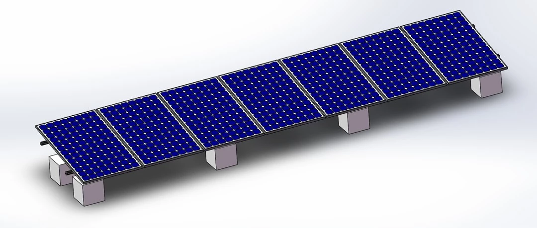
Figure 4. Schematic diagram of cement roof support scheme
1 ) solar panels quotation
No | Item | Price | Notes |
1 | Solar panel | Based on the latest solar panel price | |
2 | Inverter | Based on the latest inverter price | |
3 | Solar panel bracket | ||
4 | AC and DC cables | ||
5 | Grid-tied equipment, bridges, grounding, auxiliary device, etc. | ||
6 | Project management fee | ||
7 | installation fee, commissioning fee, etc. | ||
8 | Construction engineering | ||
9 | Tile replacement fee | ||
10 | Reinforcement fee | ||
11 | Design fee | ||
total | |||
2) Quotation for energy storage
No | Item | Specification | Unit | Quantity | Unit price
| Price
|
1 | Energy storage system | 50kWh | set | 1 | ||
2 | Battery management mystem | V3.0 | set | 1 | ||
3 | Bidirectional converter | 30kW | set | 1 | ||
4 | Cable | Corresponding specifications for each level | set | 1 | ||
5 | Distributiobox | BXB-21 | set | 1 | ||
6 | Construction and commissioning costs | set | 1 |