
This article is selected from the building photovoltaic system design guide atlas. This paper includes the classification and parameters of photovoltaic modules, the calculation of actual power of solar panels, the calculation of installed power per unit area, the calculation of photovoltaic power generation, the calculation of photovoltaic array spacing, and the actual case demonstration.
Classification of PV modules
1-1. PV modules are divided into crystalline silicon PV modules and thin-film PV modules according to the type of solar cells.
1-2. PV modules can be divided into flexible and non-flexible modules according to their appearance. The shape of flexible modules can be bent and deformed freely, and the panels of non-flexible modules generally use PV glass.
1-3. Flexible PV modules are tough and can generally withstand a bending degree of more than 30°. When used on sloping roofs, they fit the roof more closely. When using flexible modules, they should not be laid directly on the roof.
2. Composition of PV modules
2-1. Crystalline silicon PV modules are mainly composed of battery cells, interconnection strips, bus bars, glass, adhesive film, backplane, aluminum alloy frame, silicone, and junction box. As shown in Figure 2-1:
2-2. Thin-film PV modules are multi-layer film structures, mainly composed of tempered glass, transparent conductive layer, window layer (N-type semiconductor layer), buffer layer, absorption layer (P-type semiconductor layer), backplane electrode, and glass. As shown in Figure:
3. The main parameters of photovoltaic modules and photovoltaic series calculation
3-1, the main parameters of the photovoltaic module are PV module weight, PV module size, maximum power (P.), open voltage temperature coefficient (K), operating voltage temperature coefficient (K), the best working current (1.), short circuit current (1), the limit low temperature under working conditions (℃), the limit high temperature under working conditions (℃), open voltage (V), the best working voltage (Vm), positive Surface maximum static load, back maximum static load, etc.
3-2. the maximum power of solar panel refers to the working power under standard test conditions (STC). The installed capacity of the DC side of the project is the total installed capacity based on the maximum power of the PV module, such as the 5.9MWp distributed photovoltaic project on the roof of a station in Beijing, where the installed capacity of 5.9MWp is calculated by the maximum power of the PV module.
3-3. Weight and size is the main parameter for calculating the number of PV modules installed on the building roof Another main parameter is the load capacity of the building roof. The design of the building roof photovoltaic system should first calculate the roof load to ensure the normal use of the building roof.
3-4. photovoltaic module open voltage temperature coefficient, operating voltage temperature coefficient, operating conditions under the limit of low temperature, operating conditions under the limit of high temperature, open voltage, operating voltage and inverter related parameters are the main parameters to calculate the series number of photovoltaic module string. The calculation formula is as follows.


Kv-Open circuit voltage temperature coefficient of solar panel;
K'v-Working voltage temperature coefficient of solar panel;
N-Number of series of solar panel;
t-Limit low temperature (℃) under the working conditions of a solar panel;
t'-a solar panel operating conditions limit high temperature (℃);
Vdcmax-One inverter allows maximum DC input voltage (V);
Vmpptmax-One inverter MPPT voltage maximum (V);
Vmpptmin--One inverter MPPT voltage minimum (V);
Voc-Open circuit voltage of the solar panel (V);
Vpm-The working voltage of the Soale panel(V);
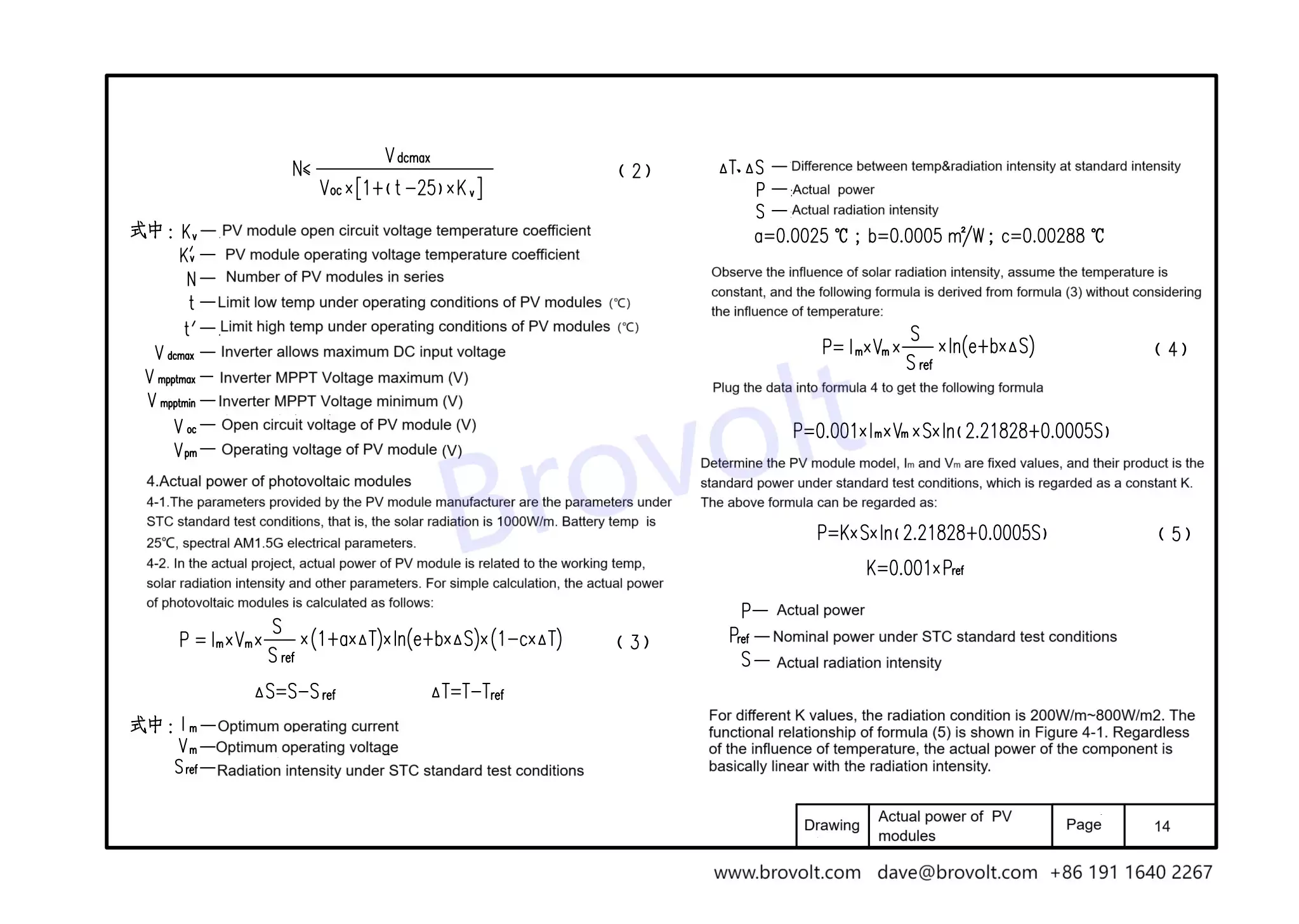
4.Actual power of solar panel
4-1. The parameters provided by solar manufacturer are the parameters under STC standard test conditions, that is, the solar radiation is 1000W/m. Battery temperature is 25℃, spectral AM1.5G electrical parameters.
4-2. Iin the actual project, the actual power of the solar panel is related to the working temperature, solar radiation intensity and other parameters. For simple calculation, the actual power of solar panels is calculated as follows:

Im-Optimum operating current;
Vm-Optimum operating voltage:
Sref-Radiation intensity under STC standard test conditions;
△T,△S-The difference between temperature and radiation intensity at standard intensity;
P-Actual power:
S-Actual radiation intensity
a=0.0025 ℃ ; b=0.0005 m/W; c=0.00288 °℃;
Observe the influence of solar radiation intensity, assume that the temperature is constant, without considering the influence of temperature, deduce the following formula from the above formula:

By substituting the data into formula (4), the following formula is obtained:
P=0.001*lm*Vm*S*ln(2.21828+0.0005S)
Determine the solar panel, Im and Vm are fixed values, and their product is the standard power under standard test conditions, which is regarded as the constant K. The above formula can be regarded as:
P=K*S*In(2.21828+0.0005S) K=0.001xPref (5)
P-Actual power;
Pref-Nominal power under STC standard test conditions;
S-Actual radiation intensity;
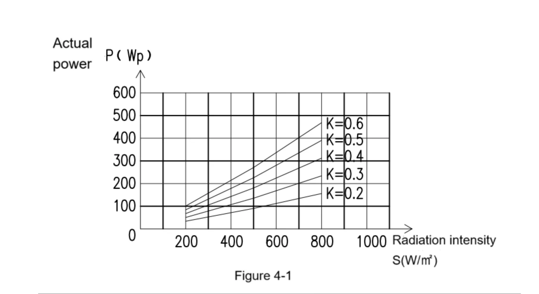
For different K values, the radiation condition is 200W/m² ~ 800W/m². The functional relationship of formula (5) is shown in Figure 4-1. Without considering the influence of temperature, the actual power of the solar panel is basically linear with the radiation intensity,The greater the radiation effect.
5.Calculation of installed power per unit area
5-1. The installation method of PV dules is mainly affected by the surroundingenvironment and building structural conditions of the project.
5-2. The installed power per unit area is determined by the component installationmethod, accounting standards and other factors.
5-2-1.Calculated by module area
Based on the module area , unit installation area of different power modules is equal tothe module divided by the module area, the calculation formula (6) is as follows.
Pe=Paz/(DxLxcosβ) (6)
Pe-Installed power per unit area;
Paz-PV installation capacity;
L-Length of inclined surface of PV array;
W- Module width;
β-PV array inclination Angle;
5-2-2.Calculated on the floor area of the project
In the photovoltaic array installation project, the installation method of fixed inclination angle is adopted, and there is a certain distance between the photovoltaic arrays, which will increase the project floor area and avoid the photovoltaic arrays affected by shadow occlusion. The calculation formula is as follows
Pe=Paz/S (7)
Pe-Installed power per unit area
Paz-PV module installed capacity
S- Total area of works
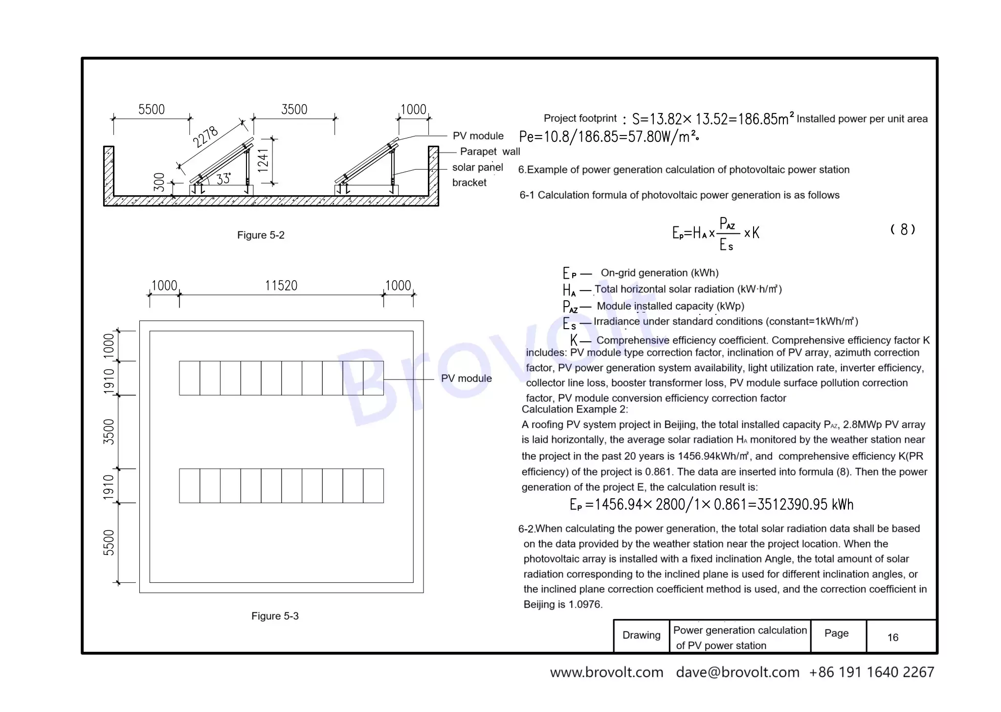
Calculation example 1: A 10.8kWp roofing PV project in Beijing adopts a total of 20 540Wp modules, which are arranged in a single row with 2 columns. Each columns quare array is composed of 10 PV modules with a tilt Angle of 33°. The project roof is a reinforced concrete roof and the direction is due south. The distance from the lowest point of solar panel to the ground is 0.3m, the parapet wall is 2m, the distance from parapet wall to the south solar panel is 5.5m, and the distance from the parapet wall tothe north solar panel is 1m. The width of PV array is 11.52m, and there are 1m wide maintenance channels on both sides of the array.
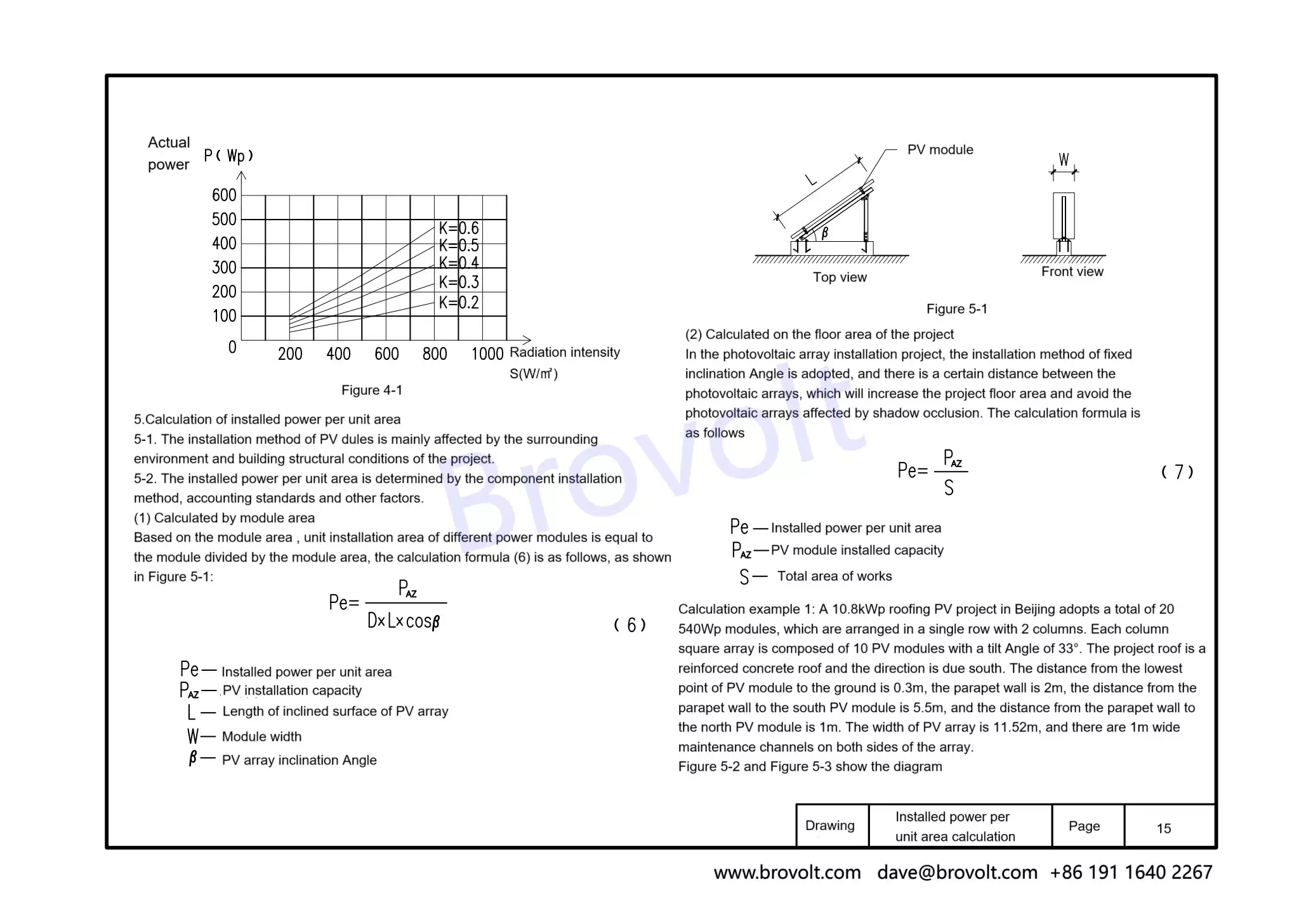
Project footprint :S=13.82x13.52=186.85㎡ Installed power per unit area Pe=10.8/186.85=57.80W/㎡.
6.Example of power generation calculation of photovoltaic power station
6-1 Calculation formula of photovoltaic power generation is as follows
Ep=Ha*(Paz/Es)*K (8)
Ep-On-grid generation (kWh);
Ha-Total horizontal solar radiation (kW·h/㎡);
Paz- Module installed capacity (kWp)
Es- lrradiance under standard conditions (constant=1kWh/m)
K-Comprehensive efficiency coefficient. Comprehensive efficiency factor K includes: solar panel type correction factor, inclination of PV array, azimuth correctionfactor, PV power generation system availability, light utilization rate, inverter efficiencycollector line loss, booster transformer loss, solar panel surface pollution correctionfactor,PV module conversion efficiency correction factor
Calculation Example 2:
A roofing PV system project in Beijing, the total installed capacity PAZ, 2.8MWp PV array is laid horizontally, the average solar radiation Ha monitored by the weather station nearthe project in the past 20 years is 1456.94kWh/㎡, and comprehensive efficiency K (PR efficiency) of the project is 0.861. The data are inserted into formula (8). Then the powergeneration of the project E, the calculation result is:
Ep=1456.94x2800/(1x0.861)=3512390.95 kWh
6-2.When calculating the power generation, the total solar radiation data shall be basedon the data provided by the weather station near the project location. When the photovoltaic array is installed with a fixed inclination angle, the total amount of solar radiation corresponding to the inclined plane is used for different inclination angles, orthe inclined plane correction coefficient method is used, and the correction coefficient inBeijing is 1.0976.
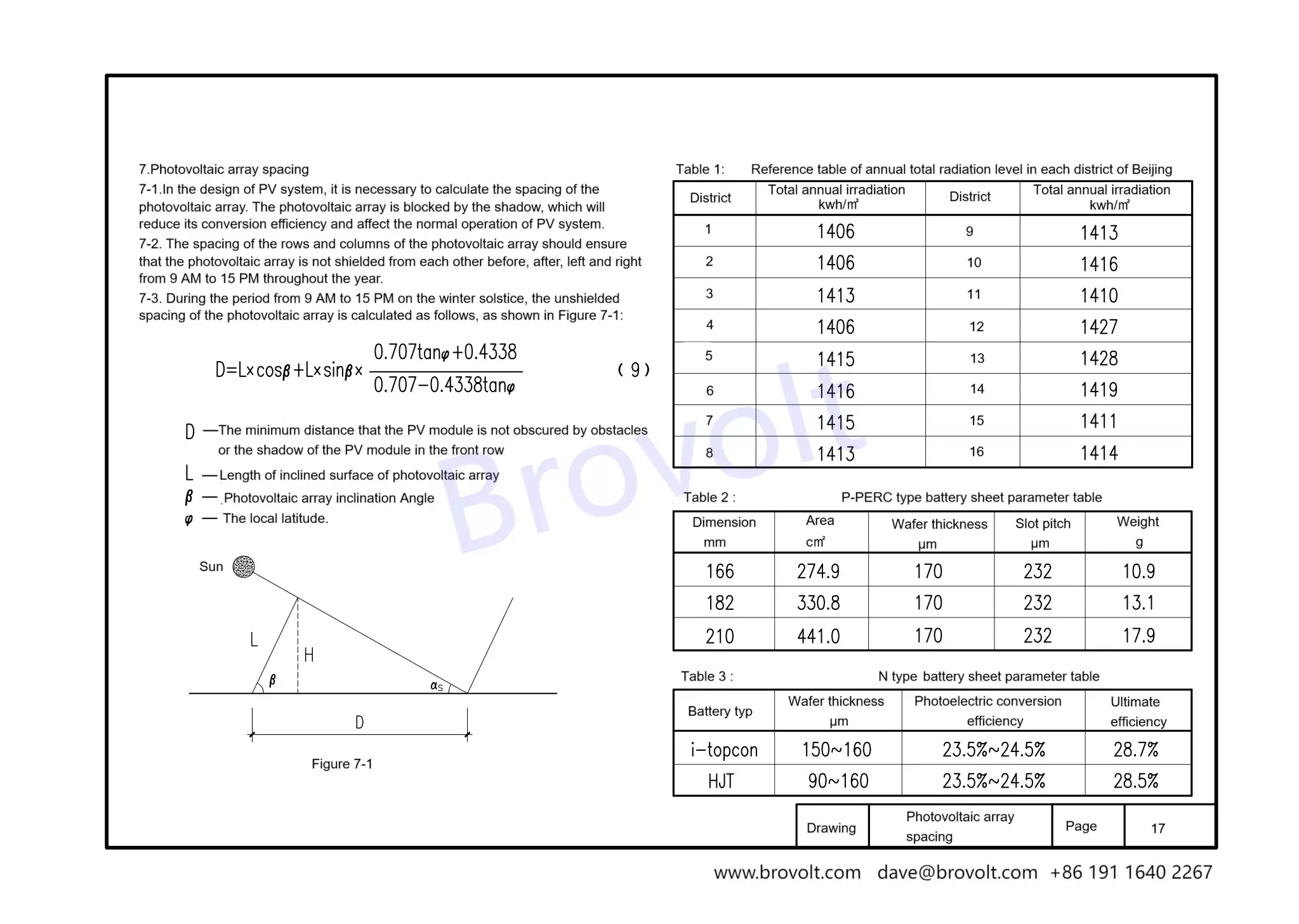
7.Photovoltaic array spacing
7-1.In the design of PV system, it is necessary to calculate the spacing of the photovoltaic array. The photovoltaic array is blocked by the shadow, which will reduce its conversion efficiency and affect the normal operation of PV system.
7-2. The spacing of the rows and columns of the photovoltaic array should ensurethat the photovoltaic array is not shielded from each other before, after, left and rightfrom 9 AM to 15 PM through out the year.
7-3. During the period from 9 AM to 15 PM on the winter solstice, the unshielded spacing of the photovoltaic array is calculated as follows, as shown 
D-The minimum distance that the PV module is not obscured by obstaclesor the shadow of the PV module in the front row
L-Length of inclined surface of photovoltaic array
β-Photovoltaic array inclination Angle
Ψ-The local latitude.
