This paper is extracted from the building photovoltaic system design guide atlas. Includes the classification of inverters, the scope of application, and a detailed demonstration of how to install inverters.
I.Inverter selection basis
1.1. "Shell Protection Level (IP code)" GB 4208
1.2. "Photovoltaic power generation grid-connected inverter technical requirements" GB/T 37408
1.3. "Photovoltaic power station access to power system technical regulations" GB/T 19964
1.4. "Electrical and electronic products basic environmental test procedures" GB/T2423
1.5. "Grid-connected photovoltaic Inverter Technical conditions" CNCA/CTS 0004
1.6. "Photovoltaic grid-connected system inverter anti-island test method" IEC 62116
1.7. Safety of Inverter for Photovoltaic power generation IEC 62109-1/2
1.8. "Photovoltaic grid-connected inverter Technical specification" NB/T32004
2. Design parameters
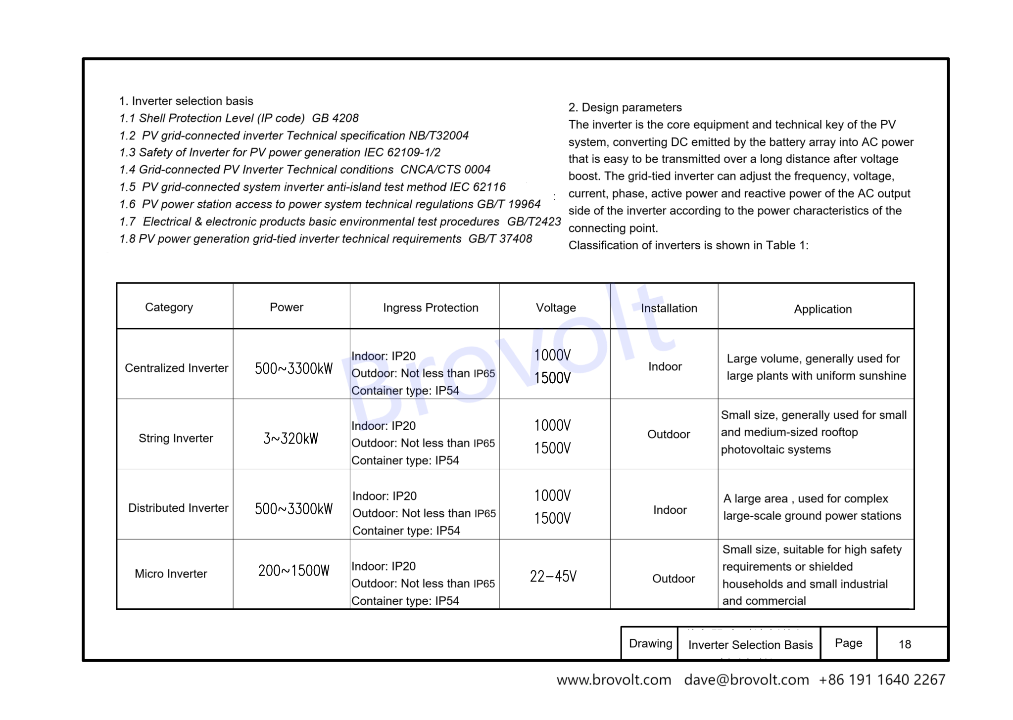
2.1The inverter is the core equipment and technical key of the photovoltaic system, converting the direct current emitted by the battery array into AC power that is easy to be transmitted over a long distance after voltage boost. The grid-connected inverter can adjust the frequency, voltage, current, phase, active power and reactive power of the AC output side of the inverter according to the power characteristics of the connecting point.
Classification of inverters is shown in Table 1:
2.2 Centralized inverter
The centralized inverter summarizes the DC generated by the photovoltaic module into a larger DC power and then inverts it. The power of this type of inverter is relatively large, and the single capacity is generally above 500KW. It has the advantages of large output power, mature technology, high power quality and low cost, but at the same time it has the disadvantage of insufficient MPPT tracking accuracy. It will affect the efficiency and electrical capacity of the entire photovoltaic power station when it encounters cloudy, shaded or a single series failure, and requires a dedicated room for ventilation and heat dissipation, so the variety is usually used in centralized large-scale photovoltaic power stations with uniform light
2.3 String inverter
Several groups of photovoltaic series for a separate maximum power peak tracking, and then after the inverter into the AC power grid, this type of inverter power is relatively small, single power is generally below 100KW, with the technical progress and cost reduction and efficiency demand is becoming increasingly prominent, the power gradually increased to 136KW, 175KW and other high-power products. It has the advantages of large number of MPPT, flexible component configuration, easy installation, high tracking accuracy, high power generation, fast operation and maintenance, but also has the disadvantages of slightly poor power generation quality and high cost, mainly used in small-scale household distributed power generation, small and medium-sized industrial and commercial rooftop power stations.
2.4 Distributed inverter
Distributed inverter realizes multi-channel MPPT optimization function by pre-controlling multiple MPPT optimizers, and adopts centralized inverter inverter after convergence. This type of inverter combines the advantages of "centralized inverter" and "decentralized MPPT tracking" of large-scale centralized photovoltaic inverters to achieve low cost and high reliability of centralized inverters and high power generation of serial inverters. According to the Sobi photovoltaic network, the distributed type is 2%-5% higher than the centralized power generation, and has better power quality, grid adaptability and lower system investment costs than the string inverters
2.5 Micro inverter
Micro inverter for each photovoltaic module for a separate maximum power peak tracking, and then through the new energy power generation after the inverter into the AC grid, this type of inverter single capacity is generally less than KW, with each component independent maximum power tracking control, in the case of shading or component performance differences to improve the overall efficiency, to minimize safety risks and other advantages. Its disadvantage is high price, more difficult to maintain after failure, more suitable for smaller projects.
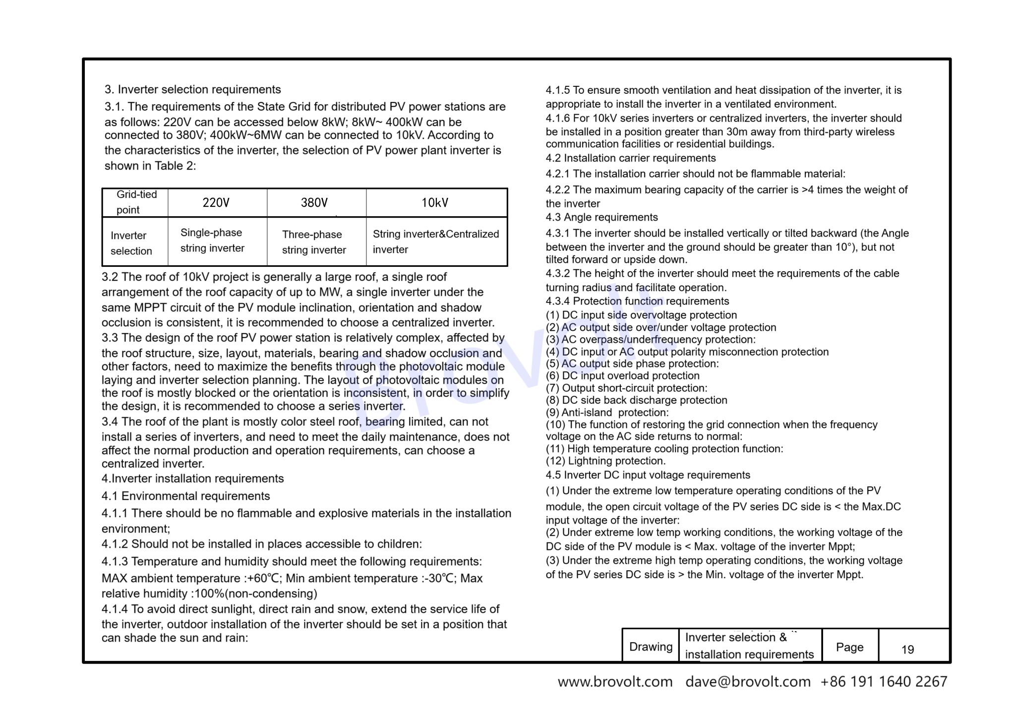
3. Inverter selection requirements
3.1 The requirements of the State Grid for distributed photovoltaic power stations are as follows: 220V can be accessed below 8kW; 8kW~ 400kW can be connected to 380V; 400kW~6MW can be connected to 10kV. According to the characteristics of the inverter, the selection of photovoltaic power plant inverter is shown in the figure:
3.2 The roof of 10kV project is generally a large roof, a single roof arrangement of the roof capacity of up to MW, a single inverter under the same MPPT circuit of the photovoltaic module inclination, orientation and shadow occlusion is consistent, it is recommended to choose a centralized inverter.
3.3 The design of the roof photovoltaic power station is relatively complex, affected by the roof structure, size, layout, materials, bearing and shadow occlusion and other factors, need to maximize the benefits through the photovoltaic module laying and inverter selection planning. The layout of photovoltaic modules on the roof is mostly blocked or the orientation is inconsistent, in order to simplify the design, it is recommended to choose a series inverter.
3.4 The roof of the plant is mostly color steel roof, bearing limited, can not install a series of inverters, and need to meet the daily maintenance, does not affect the normal production and operation requirements, can choose a centralized inverter.
4.Inverter installation requirements
4.1. Environmental requirements
4.1.1 There should be no flammable and explosive materials in the installation environment; 1.2 Should not be installed in places accessible to children:
4.1.3 Temperature and humidity should meet the following requirements:
Maximum ambient temperature :+60℃; Minimum ambient temperature :-30℃; Maximum relative humidity :100%(non-condensing)
4.1.4 To avoid direct sunlight, direct rain and snow, extend the service life of the inverter, outdoor installation of the inverter should be set in a position that can shade the sun and rain:
4.1.5 To ensure smooth ventilation and heat dissipation of the inverter, it is appropriate to install the inverter in a ventilated environment :1.6 for 10kV series inverters or centralized inverters, the inverter should be installed in a position greater than 30m away from third-party wireless communication facilities or residential.
4.2 Installation carrier requirements
4.2.1 The installation carrier should not be flammable material:
4.2.2 The maximum bearing capacity of the carrier is >4 times the weight of the inverter.
3.Angle
4.3.1 Vertical installation or backward tilt installation of inverters (the required Angle to the ground >10°), should not be installed forward or upside down:
4.3.2 The installation height of the inverter meets the requirements of the turning radius of the cable and is convenient for personnel to operate.
4.Protectionfunctionrequirements
(1) DC input side overvoltage protection
(2) AC output side overvoltage/undervoltage protection
(3) AC overpass/underfrequency protection:
(4) DC input or AC output polarity misconnection protection
(5) AC output side phase protection
(6) DC input overload protection
(7) Output short-circuit protection:
(8) DC side back discharge protection
(9) Anti-island effect protection:
(10) The function of restoring the grid connection when the frequency voltage on the AC side returns to normal:
(11) High temperature cooling protection function:
(12) Lightning protection.
5, inverter DC input voltage requirements
(1) Under the extreme low temperature operating conditions of the photovoltaic module, the open circuit voltage of the photovoltaic series DC side is < the maximum DC input voltage of the inverter:
(2) Under extreme low temperature working conditions, the working voltage of the DC side of the PV module is < the maximum voltage of the inverter Mppt;
(3) Under the extreme high temperature operating conditions, the working voltage of the PV series DC side is > the minimum voltage of the inverter Mppt.
1.5 To ensure smooth ventilation and heat dissipation of the inverter, it is appropriate to install the inverter in a ventilated environment :1.6 for 10kV series inverters or centralized inverters, the inverter should be installed in a position greater than 30m away from third-party wireless communication facilities or residential.
2 Installation carrier requirements
2.1 The installation carrier should not be flammable material:
2.2 The maximum bearing capacity of the carrier is >4 times the weight of the inverter. The Angle is required
3.1 Vertical installation or backward tilt installation of inverters (the required Angle to the ground >10°), should not be installed forward or upside down:
3.2 The installation height of the inverter meets the requirements of the turning radius of the cable and is convenient for personnel to operate. 4
(1) DC input side overvoltage protection (2) AC output side overvoltage/undervoltage protection
(3) AC overpass/underfrequency protection:
(4) DC input or AC output polarity misconnection protection
(5) AC output side phase protection
(6) DC input overload protection
(7) Output short-circuit protection:
(8) DC side back discharge protection
(9) Anti-island effect protection:
(10) The function of restoring the grid connection when the frequency voltage on the AC side returns to normal:
(11) High temperature cooling protection function:
(12) Lightning protection.
4.Inverter DC input voltage requirements
(1) Under the extreme low temperature operating conditions of the photovoltaic module, the open circuit voltage of the photovoltaic series DC side is < the maximum DC input voltage of the inverter:
(2) Under extreme low temperature working conditions, the working voltage of the DC side of the PV module is < the maximum voltage of the inverter Mppt;
(3) Under the extreme high temperature operating conditions, the working voltage of the PV series DC side is > the minimum voltage of the inverter Mppt.
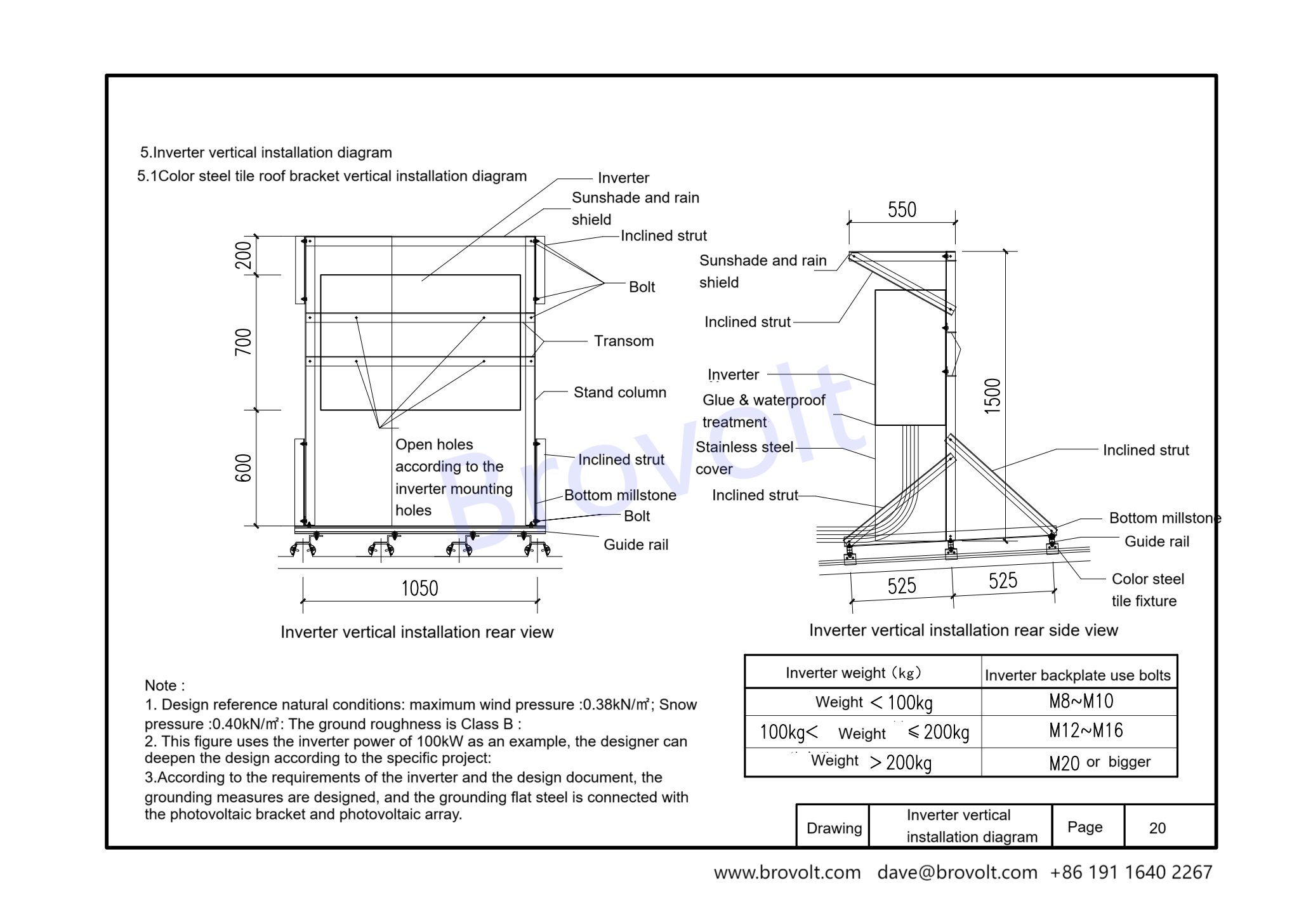
5..lnverter vertical installation diagram
5.1. This figure is suitable for vertical installation of inverters and installation of color steel tile roof brackets.
5.2. Sun shield/brace/beam/column/stainless steel shield/bottom beam/guide rail/color steel tile fixture
5.2.1 Inverter mounting holes and bolt specifications
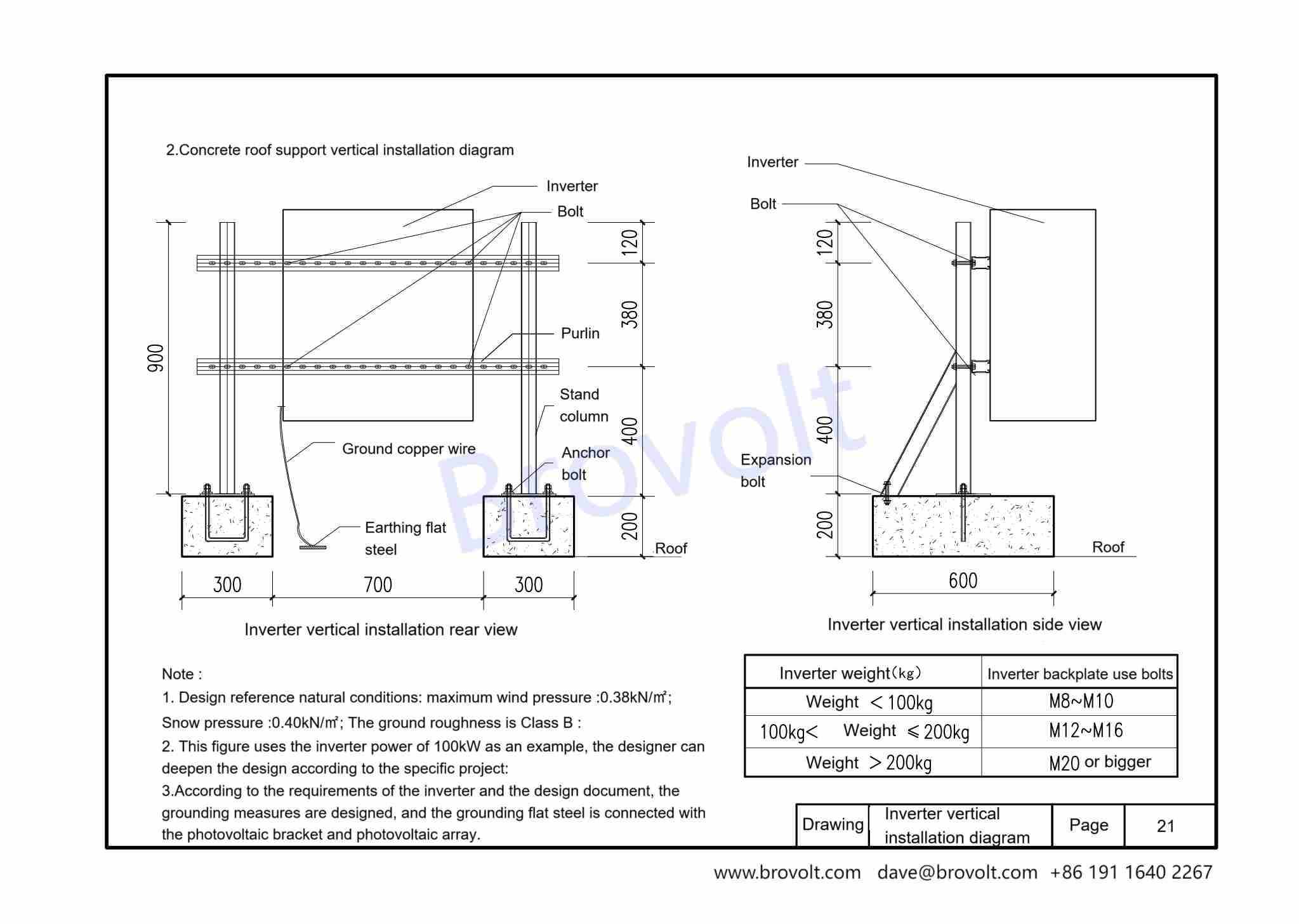
Inverter weight <100kg Bolt M8~M10
100kg ≤ Inverter weight ≤ 200kg Bolt M12 to M16
Inverter weight >200kg M20 and above
5.3. Design reference parameters
5.3.1 Maximum wind pressure: 0.38kN/m²; Maximum snow pressure: 0.40kN/m²;
Ground roughness: Class B
5.3.2 The inverter power example is 100kW, the specific project can be further designed according to the actual situation.
Grounding measures should be taken according to the requirements of the design document, and the grounding flat steel should be connected with the photovoltaic bracket, inverter and photovoltaic array.
5.4. Other installation requirements
5.4.1 The inverter back plate must be perforated according to the installation hole positions, and secured by bolts of the corresponding specifications.
5.4.2 After the column and bottom beam are installed, waterproof and glue should be applied to ensure long-term safety.
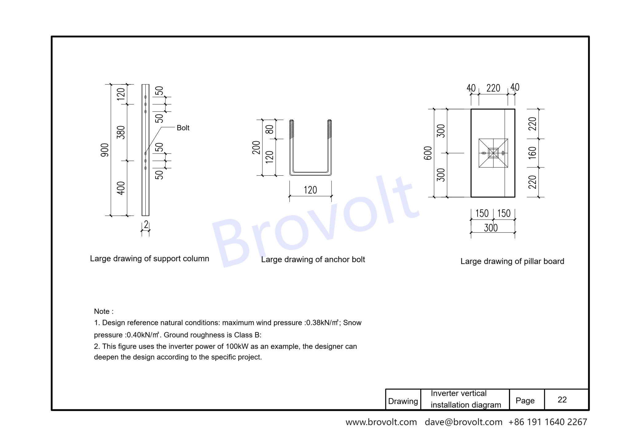
2. .Concreteroofsupportverticalinstallationdiagram
2.1. This drawing is suitable for vertical installation of inverters and vertical installation of concrete roof supports.
2.2. Mounting accessories are bolts/expansion bolts/purlins/ground copper wire/ground flat steel/post/anchor bolt
2.3.1 Design reference natural conditions: maximum wind pressure: 0.38kN/㎡; Snow pressure: 0.40kN/㎡; The ground roughness is class B.
2.3.2. This drawing uses the inverter power of 100kW as an example, and designers can deepen the design according to specific projects;
2.3.3. Design the grounding measures according to the requirements of the inverter and the design document, and the grounding flat steel is connected with the photovoltaic bracket and photovoltaic array
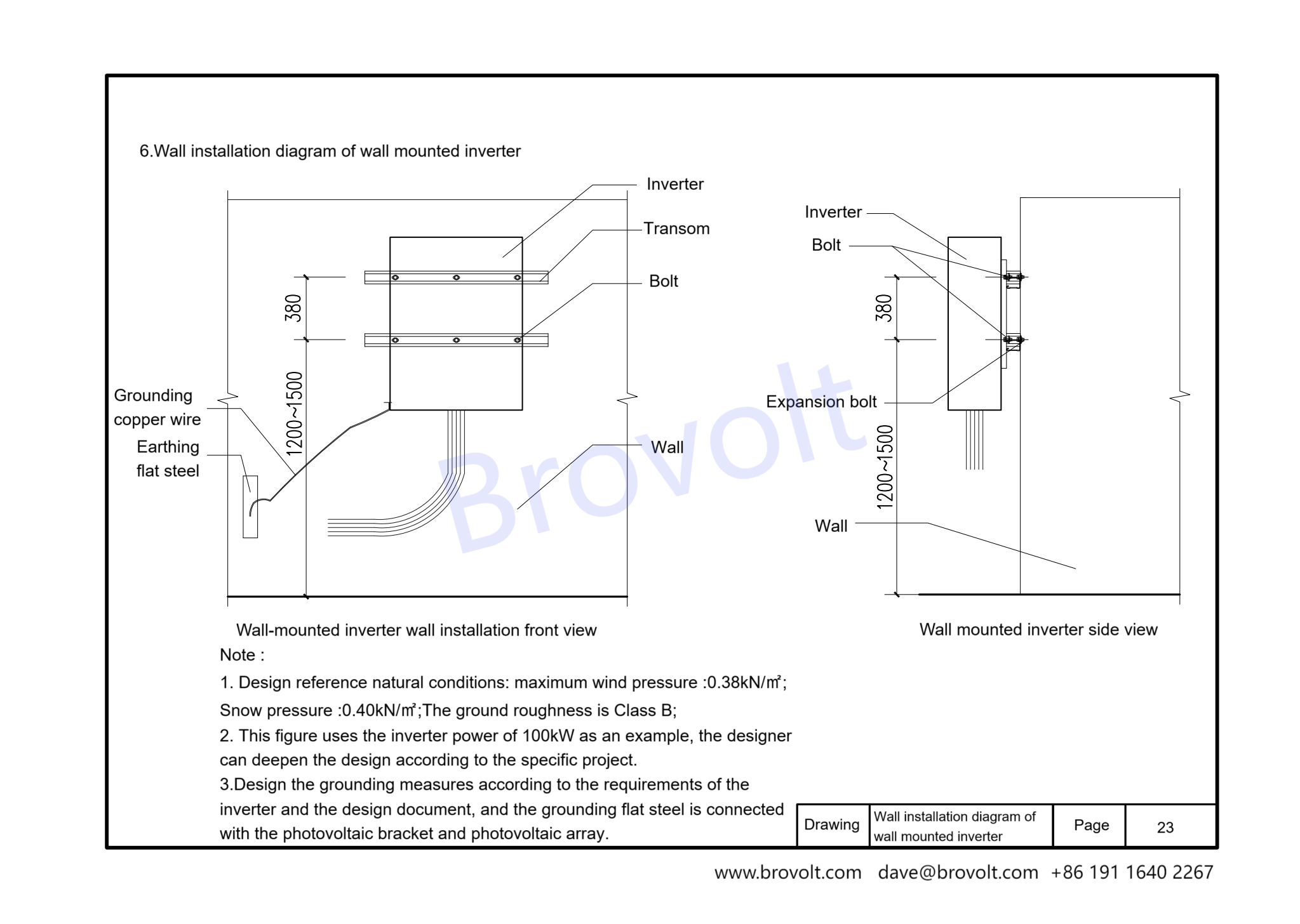
6. Wall installation diagram of wall-mounted inverter
6.1. This drawing is suitable for wall installation of inverters
6.2. Installation accessories include bolts, expansion bolts, beams, ground copper wires, and ground flat steel
6.3.1 Design reference natural conditions: maximum wind pressure: 0.38kN/㎡; Snow pressure: 0.40kN/㎡; The ground roughness is class B.
6.3.2. This drawing uses the inverter power of 100kW as an example, and designers can deepen the design according to specific projects;
6.3.3. Design the grounding measures according to the requirements of the inverter and the design document, and the grounding flat steel is connected with the photovoltaic bracket and photovoltaic array